Calibration of Tympanometers
The calibration of typanometers is somewhat more complex simply because of the range of different aspects that need calibrating. IN order to understand this complexity it is helpful to recap the basic functionality of a tympanometer. In order to measures admittance of the middle ear a low frequency tone (226Hz*) is delivered through the probe, the signal in the microphone is measured while the air pressure in the ear canal is altered by means of the air pump. The change in the measured probe tone level in the ear canal as pressure is altered gives an indication of the change in the the acoustic admittance of the middle ear. Measurement of acoustic reflexes use the same principles (without the change in pressure) to detect changes in the acoustic admittance of the ear when a 2nd acoustic signal is presented.
*high-frequency or multi-frequency tympanometers may use other frequencies as well – all should be calibrated
In order to fully calibrate a tympanometer there are a range of different measurements that must be made - the different acoustic signal levels must be calibrated as muct the conversion of the probe-tone level to impedance values.Some of the things that need measuing are listed below.
- Probe tone:
- Measure probe tone frequency and level.
- Acoustic reflex activating stimulus signals:
- Measure ipsilateral
- if available, contralateral reflex signal levels
- their frequencies and/or spectral content and rise/fall times.
- Impedance/admittance indicator:
- Measure different volumes
- Air pressure:
- Measure the air pressure range using a pressure measuring system (we won't cover this)
In most modern tympanometers the procedure is described by the manufacturer. In the example here we will use a GSI Tympstar. [For the model used the calibration mode can obly be accessed by opening the machine and changing a switch on the moterboard]. In this device an onscreen menu gives details of the calibration procedure - see figure below.
Figure 15 - calibration menu for GSI tympstar
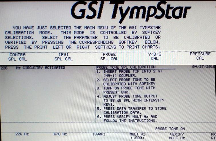
Figure 15 - entering the calibration mode on the GSI Tympstar allows you to select a range of menus which then bring up the details for calibrating that particular aspect. In this example the 'PROBE SPL CAL' menu is showing with instructions on screen and the range of different frequencies that can be selected across the bottom. Similar menus are provided for other signals. Note that the first point on the instructions says insert the probe tip into a 2ml (2cc) coupler.
Once the calibration mode is entered the tympanomer can generate the signal to be measured. This signal is measured in a 2cc coupler as shown in the figure below (different adaptors for the coupler are needed depending on the transducer. Note that it is important to disconect the air pipe before putting the probe assembly in the coupler. This is a precaution to prevent any changes in pressure (if you inadvertantly select 'pressure cal') from damaging the microphone.
Figure 16 - calibration of acoustic signald from tympanometer
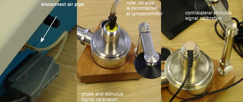
Figure 16 - Attachement of the probe assembly (middle) and contralateral transducer (right) to the 2cc coupler for measuremnet of the acoustic signals. For such measurements disconnection of the air pipe is advised so that the microphone in the coupler isn't damaged by accident.
Once the transducer is conencetd to the coupler the signal is selected from the menu and presented. The output is then measured on a sound level meter. This value is then entered in to the tympanometer menu and the inbuilt software adjusts the signal level as approrpoate.
Figure 17 - Example of contralateral reflex tone calibration
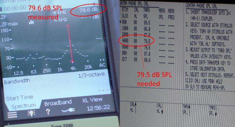
Figure 17 - Following the menu (right) a 4000Hz tone at 80 dB HL should give a measured value of 79.5 dB SPL. The actual measured value in this example is 79.6 dB SPL.
After you have calibrated the probe tones the instructions will ask you to calibrate the conversion o fthe probe signals to various components of acoustic impedance. This is done by playing the signals into acoustic cavities of fixed sizes. In the GSI Tympstar three separate components of impedance can be measured:
- Ya – Acoustic Admittance* (the reciprocal of acoustic impedance)
- Ba – Susceptance (imaginary component of complex acoustic admittance)
- Ga – Conductance (real component of complex acoustic admittance )
* Admittance is a vector quantity that can be broken down into 2 components – real and imaginary - one way of thinking about these are as 2 measurements that have a 90 degree difference in phase)
Figure 18 - YBG calibration
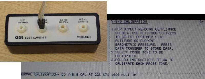
Figure 18 - For YBG calibration the set of test cavities provided by the manufacturer are used, the probe is inserted into these in turn and the signal played as appropriate (according to the instructions given). It is this process that enable the tympanometer to accurately measure things like ear canal volume as well as the YBG components.