Airway Reopening: The propagation of an air finger into a
collapsed elastic tube
Background
Many pulmonary diseases result in the collapse and occlusion of
parts of the lung with viscous fluid. The
subsequent airway reopening is assumed to occur via the propagation of
an `air finger' into the collapsed, fluid-filled part of the airway.
The problem has some similarity to the scenario of the `first breath'
when air has to enter the fluid-filled airways of a newborn baby for
the first time. Due to the complex nature of the three-dimensional
fluid-structure interaction which governs this problem (a free
surface flow interacting with a strongly collapsed elastic tube),
the mechanics of airway reopening are still poorly understood.
The Mathematical Model
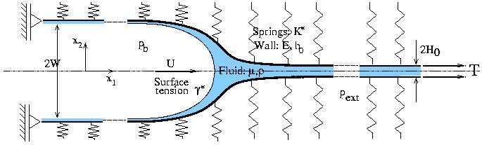
The figure below shows a conceptually simple mathematical model of
airway reopening, first proposed by Gaver et al. (JFM
319, 1996): A positive bubble pressure pb
drives an air finger into a fluid-filled 2D channel whose walls consist of
thin elastic beams under large axial tension T. The walls are
supported laterally on an elastic foundation which represents the
parenchymal tethering.
Finite Reynolds number effects
Gaver et al. studied the problem at zero Reynolds number using a
boundary element method. We re-investigated the problem, using a
Finite Element solution of the fully coupled fluid-structure
interaction problem. which allowed us to study the effect of fluid
inertia on the system's behaviour.
The pressure/flow relationship
The figure shows the channel width W, far behind the bubble tip
as a function of the
non-dimensional propagation speed of the bubble (expressed in terms of
the capillary number Ca). Since the channel width W is proportional to
the bubble pressure pb, the results show that even at these
relatively modest Reynolds numbers (of about Re=10-15), fluid inertia
strongly increases the bubble pressure pb required to drive the air
finger at a given speed U.
The flow field
Fluid inertia also has a strong effect on the flow field and the
corresponding wall deformation: For sufficiently high Reynolds
number, the wall develops a noticeable wavy deformation pattern in the region
ahead of the bubble tip. The high velocity
fluid that passes through the relatively narrow `neck', which is formed
by the maxima of the wavy wall displacement field, impinges on the
relatively stagnant fluid ahead of the bubble tip. This can cause
the air-liquid interface near the bubble tip to bulge out as shown in
the figure below.
The figure shows the streamlines in a frame
of reference moving with the bubble tip and the colour contours
represent the absolute velocities |u|. Re=15, Ca=2.0.
Page last modified: September 28, 2000
Back to Matthias Heil's home page.